Note
Installing USB-C Charging and Side Rails on My KX2
A first-pass walkthrough of adding USB-C charging and protective side rails to a new Elecraft KX2.
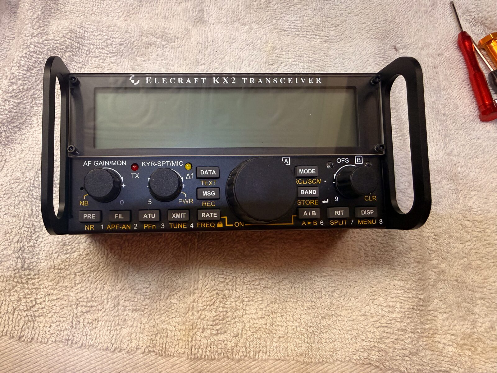
I finished two small upgrades to the KX2: the KXUSBC2 internal USB-C charger from G7UFO and the Side KX rails from Gems Products. The KXUSBC2 replaces the KXIBC2 that came factory-installed in this radio, using the same side-plate location to add USB-C charging. The rails replace the stock side plates with protective handles, which should make the radio easier to pack for portable operating without worrying as much about the knobs and front panel.
This is a field note, not a replacement for the manuals. I am not a serious tinkerer, and opening up a brand-new radio still makes me pause. The install went fine, but it was not a mindless follow-the-pictures job either. My KX2 was manufactured in mid-May 2026, and one bit of the right-side hardware did not look like the manual photos. The useful part of this note is probably that moment: slowing down, comparing the parts in front of me to the instructions, and figuring out what Elecraft changed.
At a glance
- Radio: Elecraft KX2, manufactured mid-May 2026
- USB-C charger: G7UFO KXUSBC2
- Rails: Gems Products / Gem’s Products Side KX for the KX2
- Extra parts: non-rail KXUSBC2 side plate, plus an uninstalled Pro Audio Engineering heatsink
- References: the KXUSBC2 project notes and the Side KX KX2 manual
- Why: USB-C charging in the radio and better side protection for portable operating
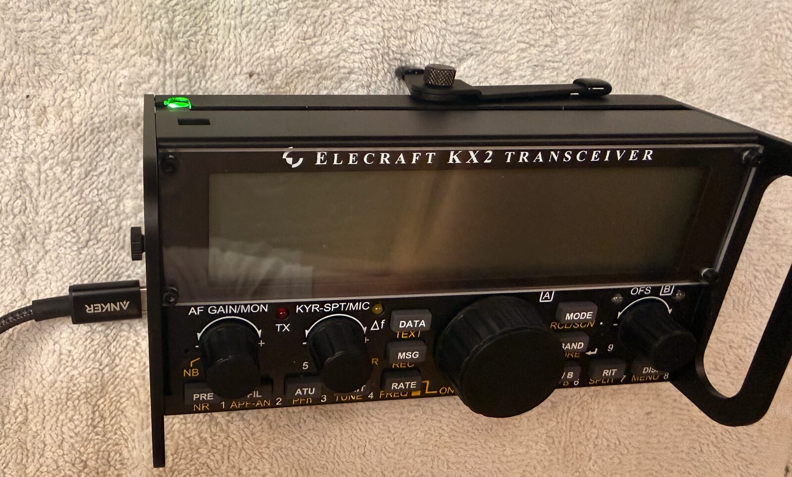
- Result: USB-C charging worked; the charge indicator glowed green after plugging in a USB-C charger
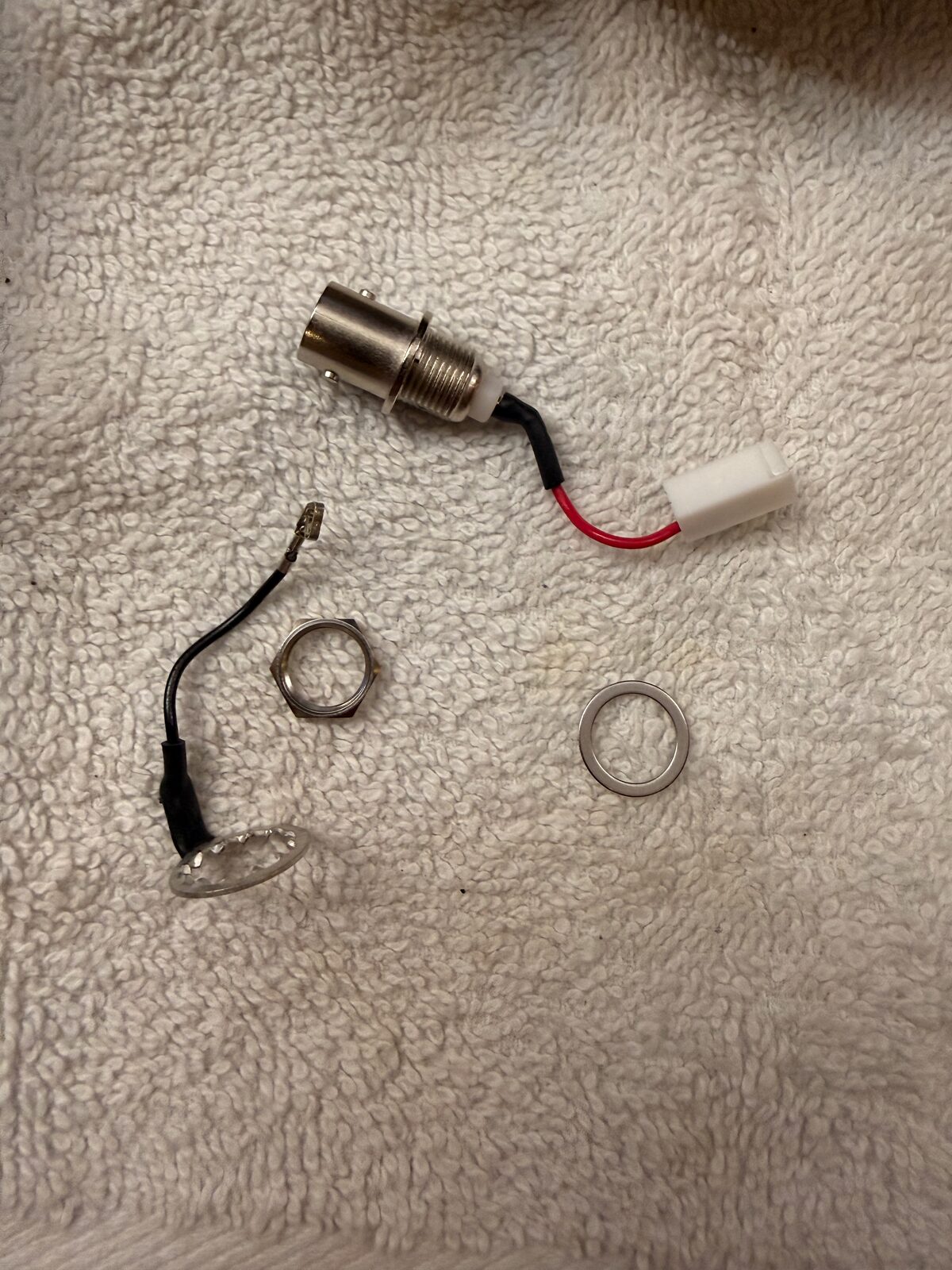
The parts
The G7UFO kit includes the charger board and a replacement side plate. I also bought the protective rail version for that same side, plus the matching rail for the other side of the radio. Before taking anything apart, I laid out the parts and took a few photos so I could tell which screws, washers, and plates came from which kit.
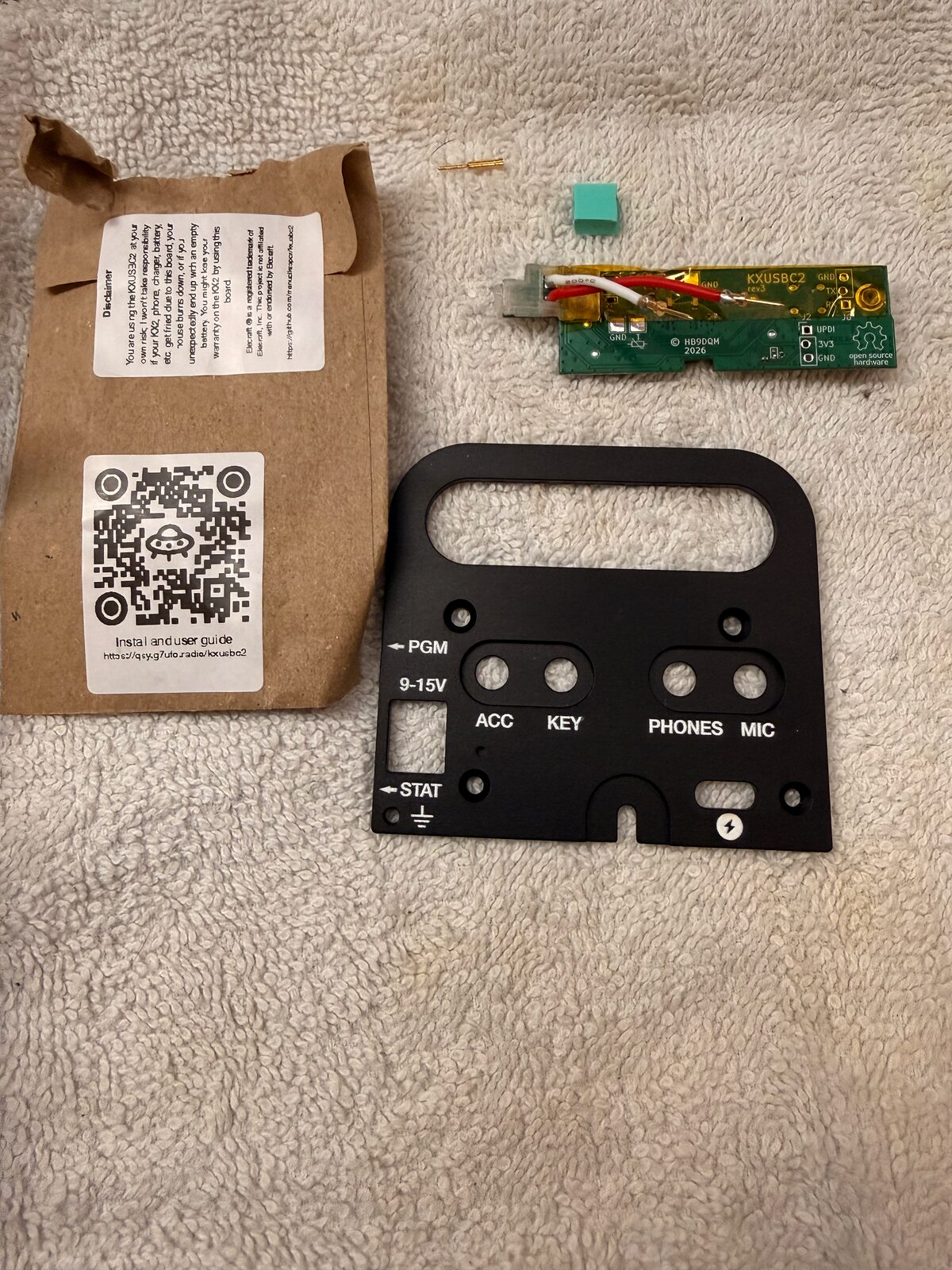
That was worth doing. There are enough small screws, washers, thermal pads, and connectors involved that I did not want to rely on memory once the radio was open. It also means I have the normal non-rail KXUSBC2 side plate left over if I decide later that the handles are more than I want for a particular pack or trip.
I also picked up the Pro Audio Engineering heatsink, but I left it out for now. It adds a few ounces, and most of my portable activations are five-watt CW/SSB outings rather than long digital-mode sessions. For now I would rather keep the KX2 light. If I start pushing it harder, especially on digital modes, I already have the heatsink and can add it later.
Opening the KX2
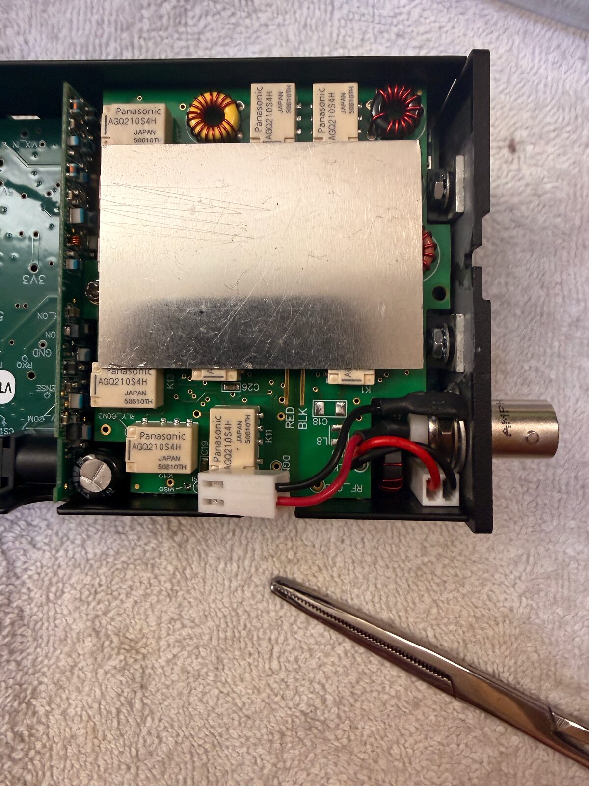
I worked on a towel and treated the first part as slow disassembly: battery out, side hardware off, screws kept together, and no tugging on small internal connectors.
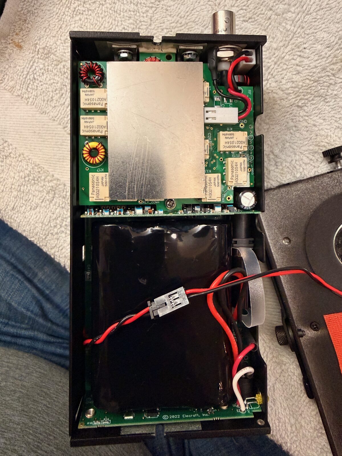
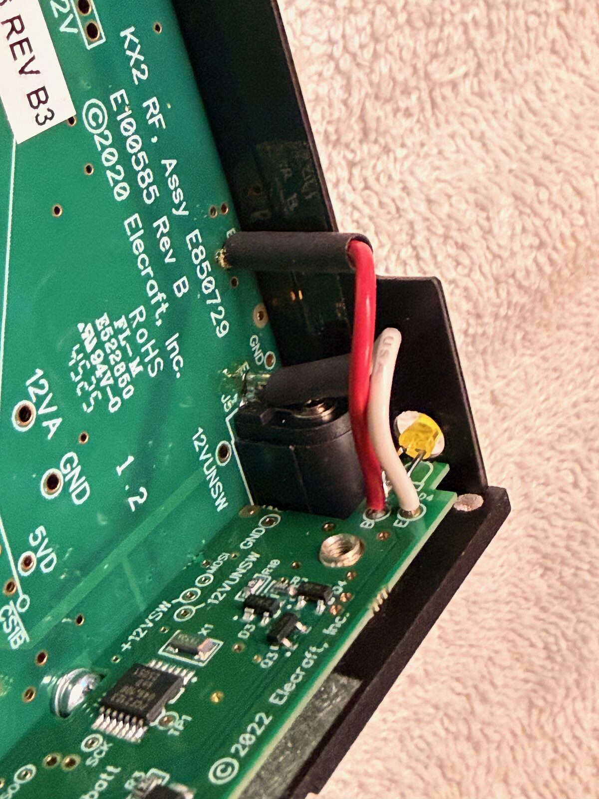
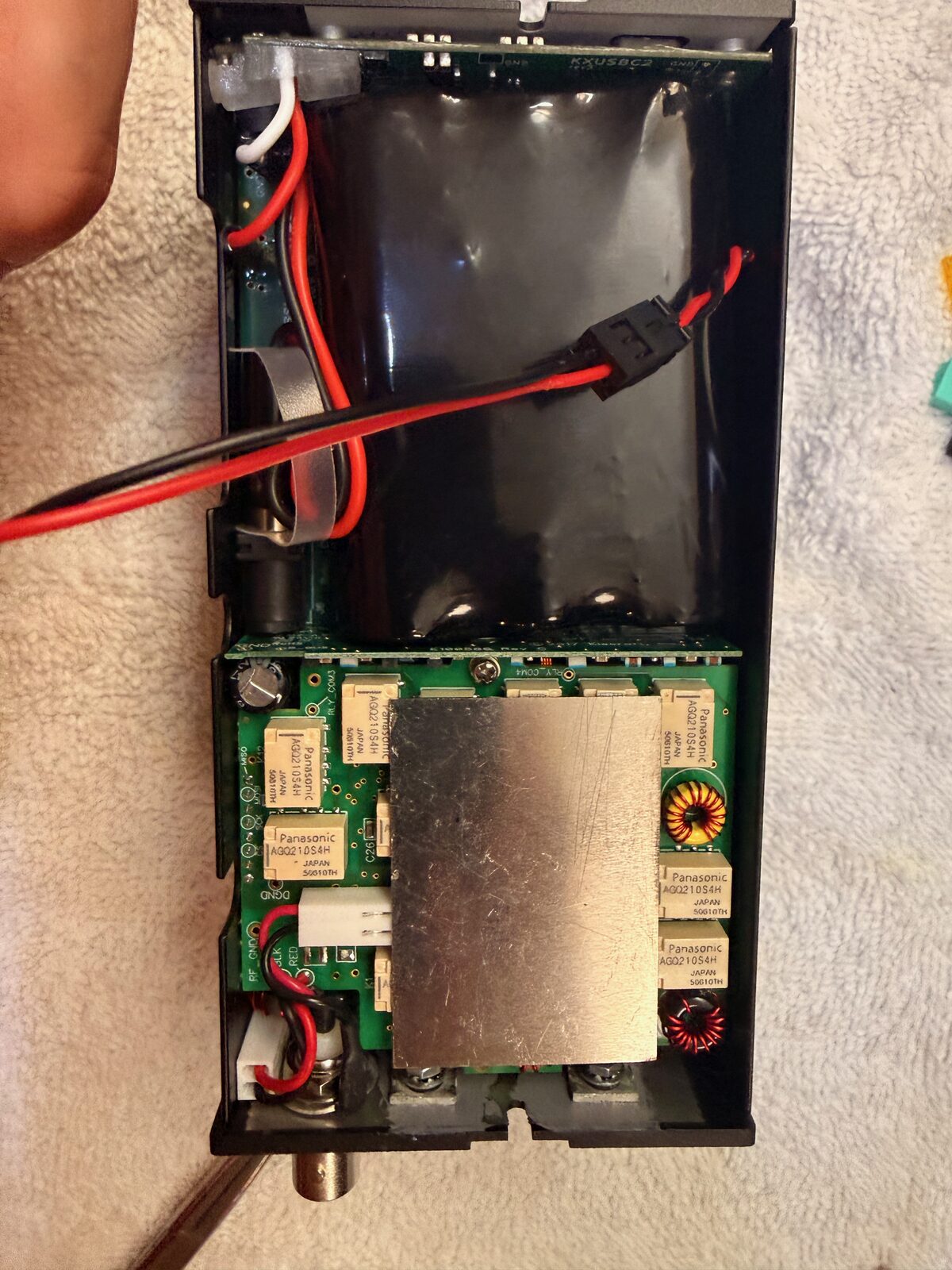
The KXUSBC2 uses the same two RF-board connection points as the factory charger
board. In my radio the visible labels were B and E, and the replacement
board had matching red and white wiring. This was simple enough, but I was glad
I had photographed the original routing before disconnecting anything. A phone
photo is cheap insurance when the radio is open on the bench.
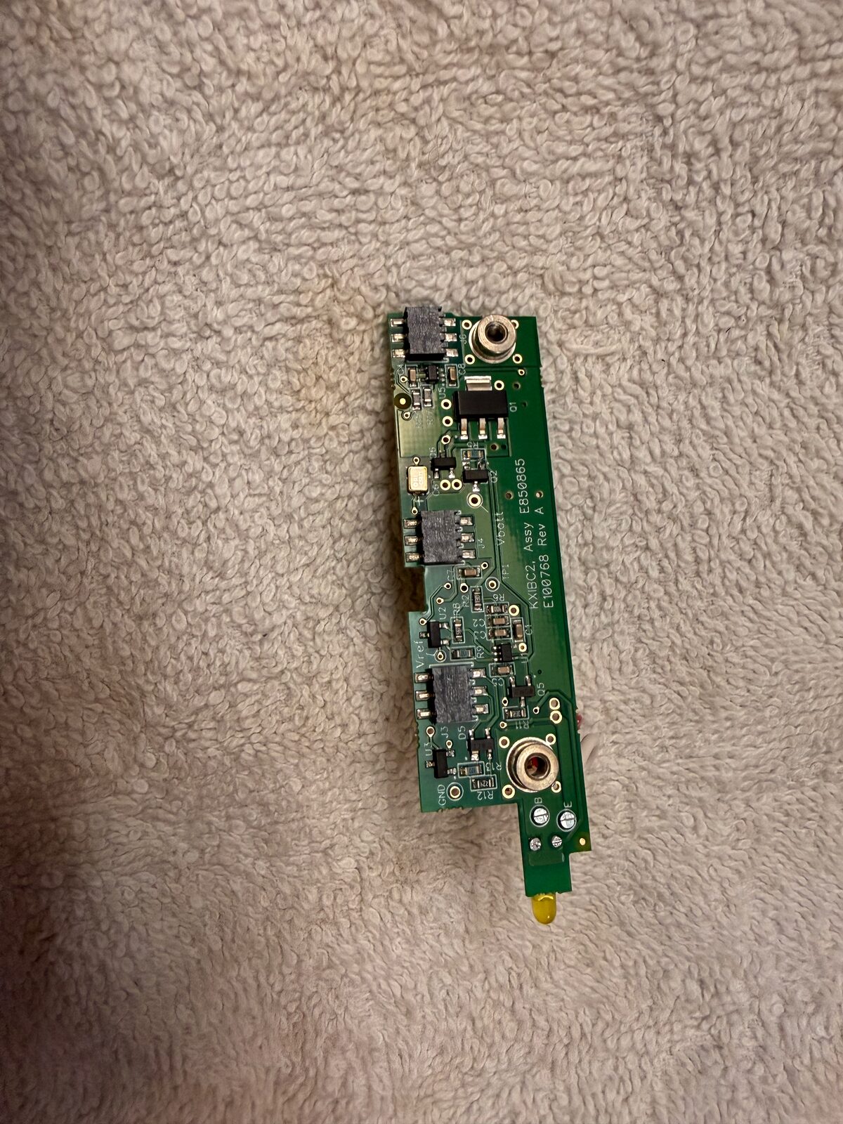
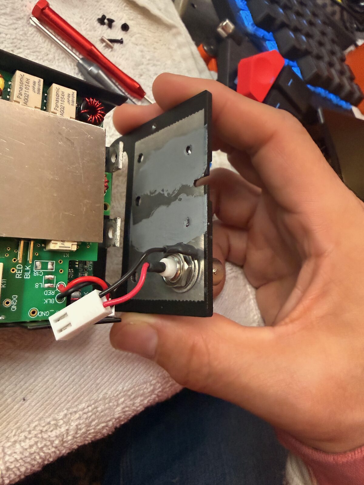
The stock side plate
The factory KXIBC2 side plate came out as a small assembly with the connector wiring, thermal material, and heat-transfer surfaces still attached.
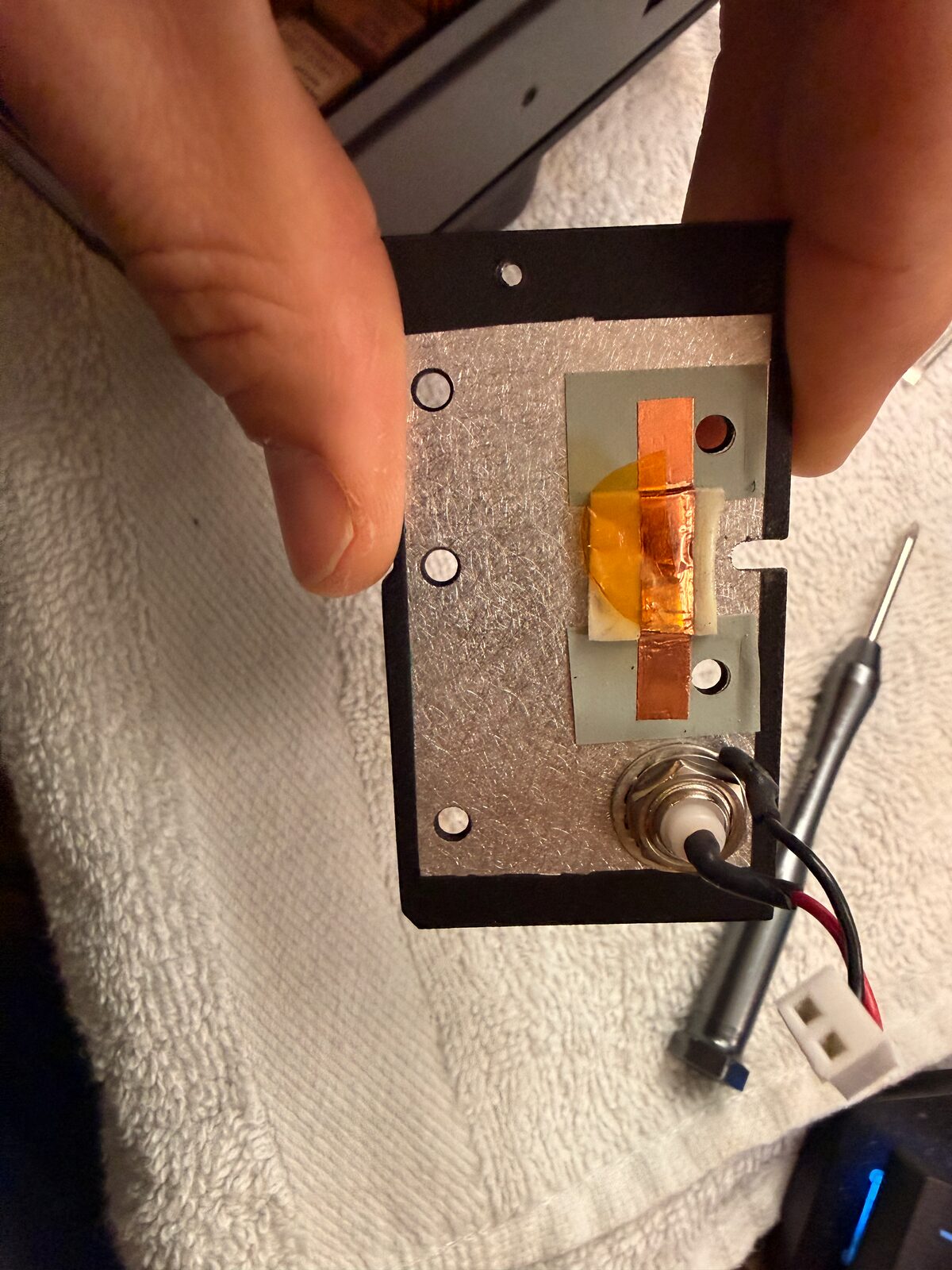
This was the first place where “remove the side plate” covered more detail than I expected. The parts are small, the clearances are tight, and the plate has enough bits attached to it that I wanted to understand what was structural, what was thermal, and what was simply coming along with the old assembly.
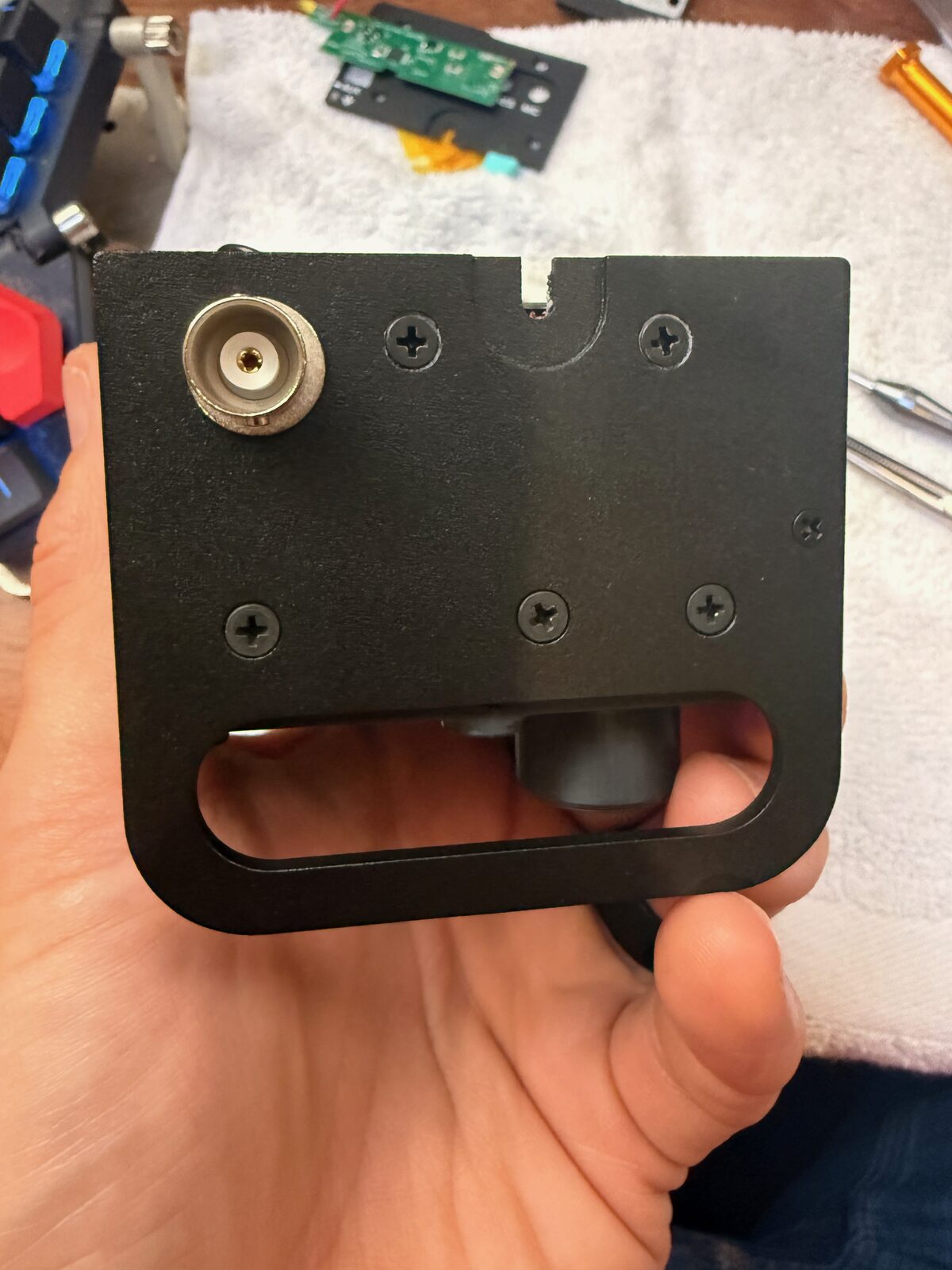
The newer KX2 screw difference
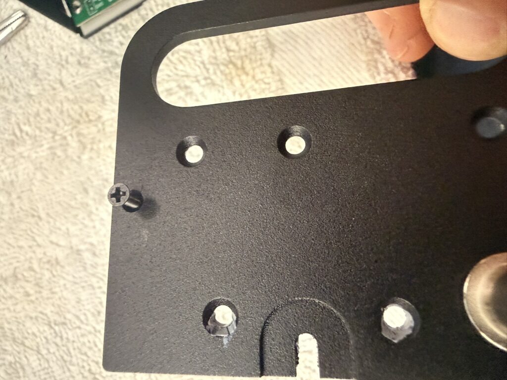
The trickiest part on my radio was one right-side screw/fastener arrangement that did not look like the pictures I was using. My KX2 was built in mid-May 2026, and the area around the PA/heatsink/side plate matches the newer mechanical revision that Gems Products notes for KX2 radios after serial number 5441, roughly since May 2025.
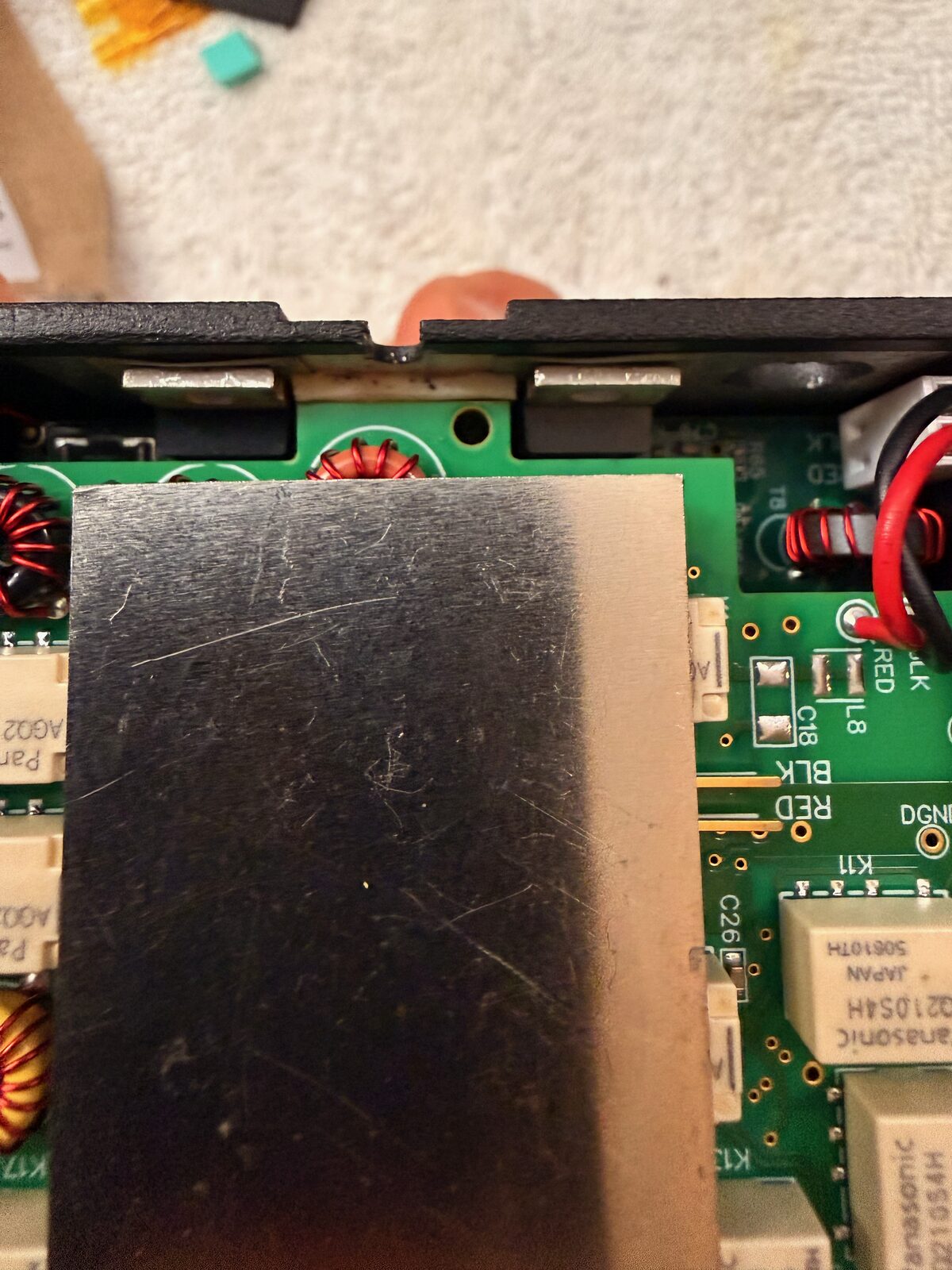
The manual described a small screw with only a few threads. On my radio, the part behaved more like a longer screw threading into a small barrel-shaped standoff. I would call it a threaded standoff or internally threaded spacer: not a normal nut, but a little sleeve with threads inside it. As far as I can tell, it is only receiving that screw. The screw does not pass all the way through the standoff and attach to something on the other side.
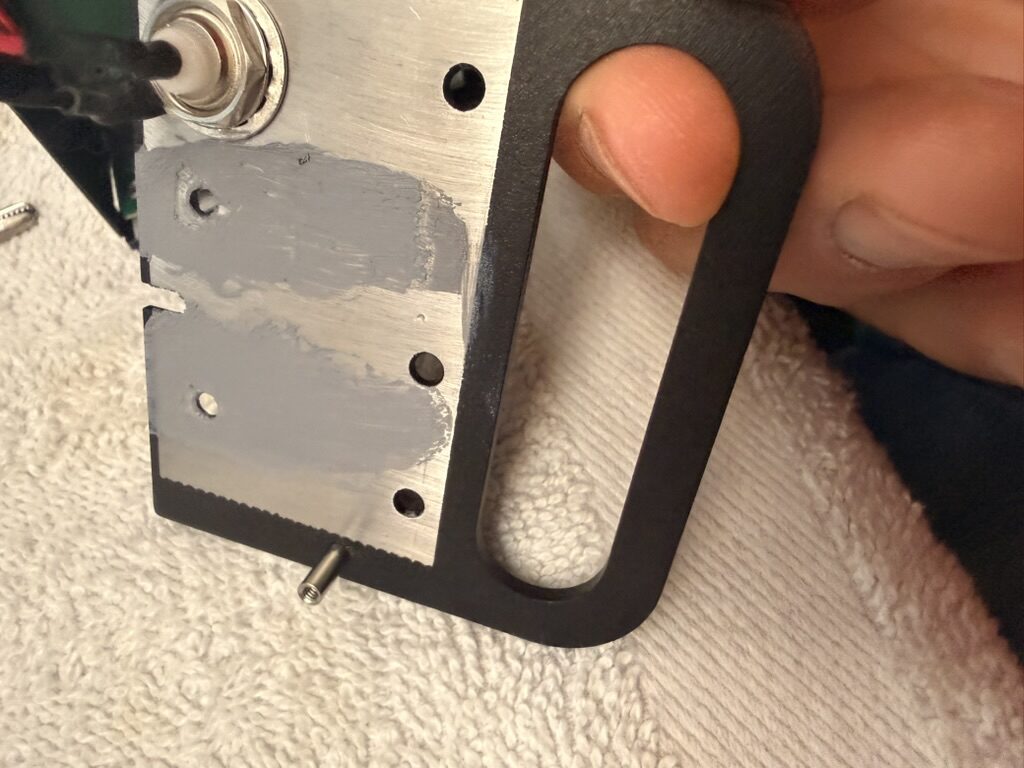
That was the moment where I had to stop treating the manual photo as literal and look at what the radio was actually doing. Once I realized that the longer screw and standoff were the newer version of the same attachment point, the rest of the install made sense again. The important thing was not to force it.
Moving the thermal interface over
The Side KX plate still needs to preserve the thermal path that the original side plate provided. I reused and moved the thermal material as instructed, then checked the coverage and alignment before reassembling the side.
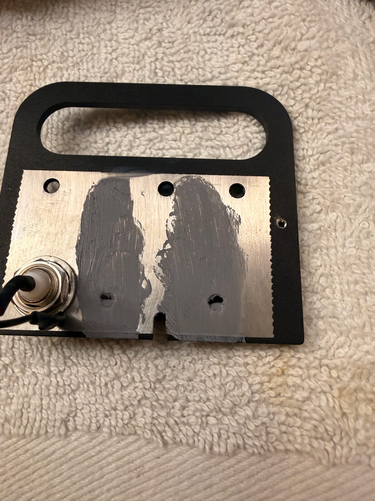
This was another place where going slowly mattered. The rail is a mechanical upgrade, but it still has to behave like the original side plate electrically and thermally. I did a dry fit before tightening everything down so I could make sure the wires were not pinched and the plate was seating correctly.
Fitting the rails
Once the side-plate details were sorted out, the rail install was mostly the kind of mechanical work I expected: line up the plates, confirm the connector openings, and tighten the hardware evenly.
I checked the fit from a few angles before closing the radio. Nothing should bow, the connector openings should line up, and the internal wiring should still have a natural path. That is all obvious once the part is seated, but it is much easier to catch before the case is back together.
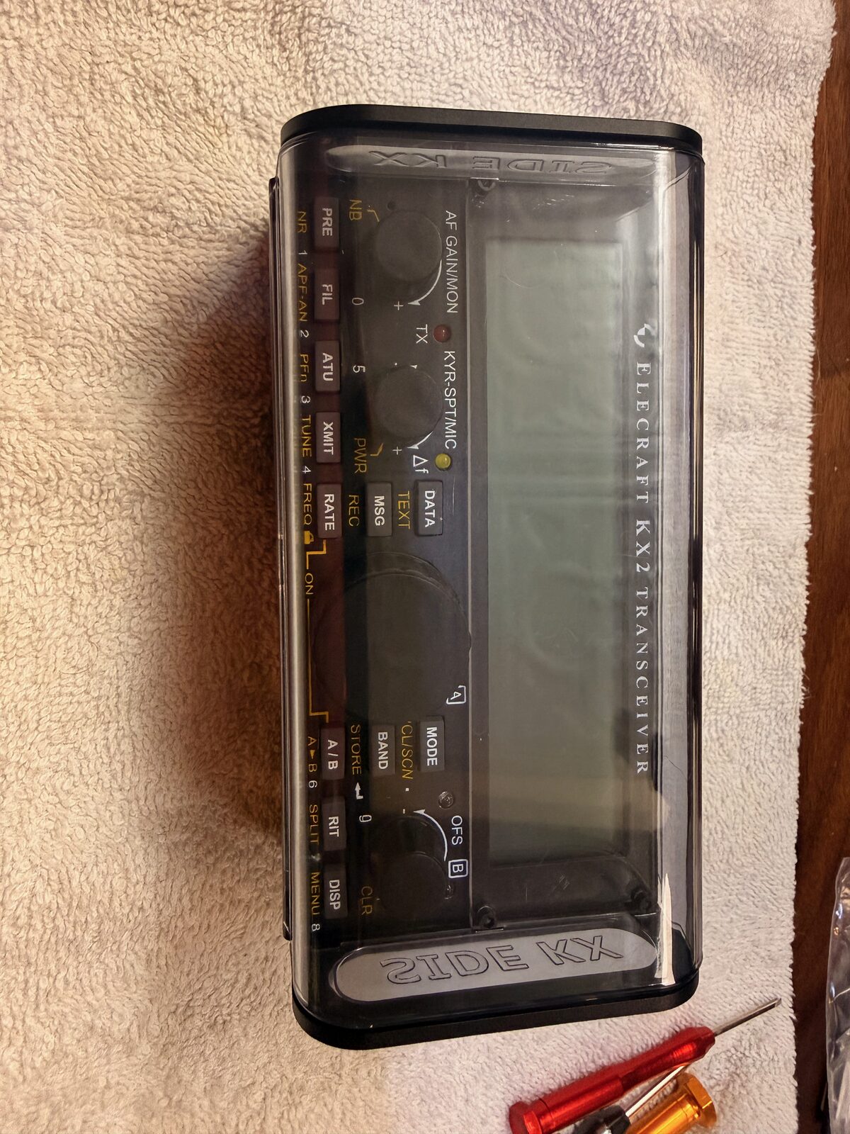
Closing the radio
After the internal checks, I reinstalled the battery cover and looked over the radio from the front, back, and sides. The rails make the KX2 look a little more field-ready, and they give the radio a much better handhold without adding a lot of bulk.
The last real test was simple: plug in USB-C power and see whether the charger behaved.
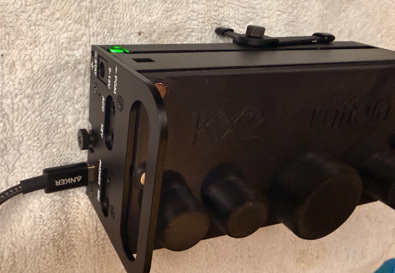
It worked. I plugged in a USB-C cable, got the green charging light, and the radio looked happy. The first real field use came later that morning during a Pack Mule activation at JL Curran State Park. That does not make the install fully proven yet, but it did get the radio through a normal portable CW outing.
What I would do the same way again
- Take photos before disconnecting anything.
- Keep the original screws and small parts organized by side and step.
- Treat the instructions as the source of truth, but compare them against the actual radio before forcing any part.
- Dry-fit the rail before tightening the hardware.
- Check USB-C charging before putting the tools away.
What I still want to verify
- Do a longer charge cycle and a few more portable operating sessions before calling the install boringly complete.
- Decide after a few activations whether the rail handles stay on full time or whether I prefer the normal side plate for some trips.